
Updated 10/23/2022. While stationed on Midway Island in 1971-1972, I operated as KM6DY, with an early model Yaesu FT-101 and a home made vertical on the roof of the apartment. The Navy decided to dump two old (1952) 10KW AM beacon transmitters into the ocean and replace them with modern units. I convinced the communications officer to allow me three days to pull parts off these transmitters before they dumped them and from these parts I built a 4-1000A linear amplifier.
I used that amplifier for nearly thirty years in various locations until the HV transformer secondary shorted to ground and then I gave most of it to someone who really wanted a linear and had the parts and talent to replace the HV system.
So I’ve been low power since about 2002 but have lots of parts and some 813’s which beckon to me. I am neither an engineer nor technically trained so my electronics knowledge is self-obtained and has lots of holes in it. Thousands of 813 amplifiers have been built so there is no new technical information here, but I’ve pulled together information from many sources. I’m using the simplest circuit I could develop; it seems fairly bullet-proof.
I selected 813’s for several reasons:
1) They are very rugged and forgiving tubes; especially the ones with graphite (not steel) plates.
2) They are low cost, and I already had one and found another graphite NOS one for $25. I have a third with a steel plate and might do something with that later.
3) Alternatives like 572B, 3-500Z or 4-400 cost far more, are more delicate and less forgiving than 813’s.
4) The antenna and the receiving station don’t care how the watt is generated – Solid State, Class E or an old 813 tube. A watt is a watt.
5) On the receiving end, there is usually no audible difference hearing a 1KW or a 1.5KW transmitter, so 1 or 1.2KW from a pair of 813’s is OK.
6) I’m a cheapskate; if I ruin one I can probably find another for $25.
Here’s a page about killing parasitic oscillations in the Linear Amp’s final tubes!
Here is a .pdf download of the 813 data sheet.
Here is a .pdf download of the RF Deck Circuit.
Note how simple the preliminary circuit is and that all three grids are strapped directly to chassis ground, essentially turning the tubes into triodes. There is no loss of wattage in the triode configuration and this eliminates the need for grid bias circuitry and metering. It’s the simplest circuit I could find and many like this have been built.
The point of having a 0.01 capacitor from grids to ground in older designs, is to “tune out” the tiny inductance of the tube’s internal grid-to-pin connection wire. But it is not at all clear that 0.01 is the exact value needed to neutralize this inductance for all 813 tubes from various manufacturers. Strapping the grids directly to ground avoids any questions.
Here is a .pdf download of a plate voltage meter schematic.
Here is a .pdf download of a plate milliampere meter schematic. Be aware that for both meters, your dropping resistor values might have to be different, depending on the meter scale/ohms and the B+ voltage. Measuring the plate voltage this way is much safer than putting the meter directly into the 2500 volt HV line.
Here is a .pdf download of the Power Supply Circuit.
Here is a link to a December 1982 Ham Radio Magazine article (Word download), courtesy of K7WES, describing an amplifier like this one. The article is a bit technical but the schematic is clear and studying the text provides a lot of information.
Here is an old QST article that describes an amplifier and provides a schematic, which I am generally following except that I’m strapping all grids to chassis ground.
I’m also taking tips from “The Junker Amplifier,” a Lew McCoy ARRL project (.pdf download). Differing from this QST article, I have made safety improvements to the HV and plate current metering circuits and strapped all grids to chassis ground.

 I bought three old tube HP UHF signal generators for a total of $15 at the Raleigh Hamfest. Parting out the first two yielded a large number of useful parts, mostly for other projects. Now, both a revised power supply and the amplifier will fit in the newly-acquired and refurbished HP cabinet instead of being in separate cabinets.
The empty cabinet, viewed from the front, shows that it is ventilated on both sides, the bottom and the back. A 4″ repurposed computer fan will blow directly onto the tubes; this, plus all the cabinet ventilation, should be satisfactory. We’ll see; each filament is like a 50 watt lightbulb and then we add the plate dissipation – the cabinet should be quite warm!
In a Grounded Grid configuration, all grids are tied to ground so the tubes should be stable, reducing the potential for IMD, oscillations and other bad events. Note that a commercial suppressor is installed in the grid lead (this was a hamfest find: $5 for 5 units!). This is expected to kill parasitic oscillations and eliminate the need for plate parasitic suppressors. If it doesn’t work, I’ll install typical plate suppressors.
It should produce about a KW input, depending on how the plate voltage turns out. I’m building it because I have all the parts and like to build…I don’t operate much. Photos of some of the parts are below:


20 meters and up seem to be coming back to life as the sunspot cycle improves. With a quality coil in the pi-network and the size of the tune and load capacitors, it will probably work well at least from 80 to 15 meters and possibly on 10 as well.
It would need more inductance in the tank circuit to reach 160M; I might add a toroid to provide that; we’ll have to see; or perhaps the spare steel-plate tube that I have would make a stand-alone 160 meter amp.
A grounded-grid configuration results in about 10x amplification, whereas a grid-driven circuit could produce around 22x with a much lower drive requirement. However, since I have 80-100 watts of drive from my Yaesu 840 xcvr and more from a 2×807 or 2x6146W xmtr that I plan to build, I’ve selected grounded-grid.
It will be used mostly for SSB and CW service but would also provide perhaps 100 watts of AM input as well, if I can drive it with enough AM. It will be very inefficient (25%?) on AM but who cares.
 I separated the HP’s chassis from its side panels by drilling out the rivets and replaced it with an exact-size used one that I had – what luck! A back panel was cut and installed. It is not necessary for the build but I wanted to stiffen the entire chassis due to the weight of the HV xfmrs, filament xfmr, filament choke and other items. The HP’s chassis side panels were modified and retained since these fit the cabinet’s built-in guides that allow sliding the whole thing into the cabinet.
The left side of the chassis that holds the under-mounted heavy power transformers was reinforced with a 3/16″ thick aluminum plate that I cut on my table saw; see photo below.

This photo shows how the two microwave oven HV transformers (MOT) are mounted upside down under the chassis. More about these later.
The metal work for the chassis and panel was done with hand tools so it’s not perfect but it’s good enough.
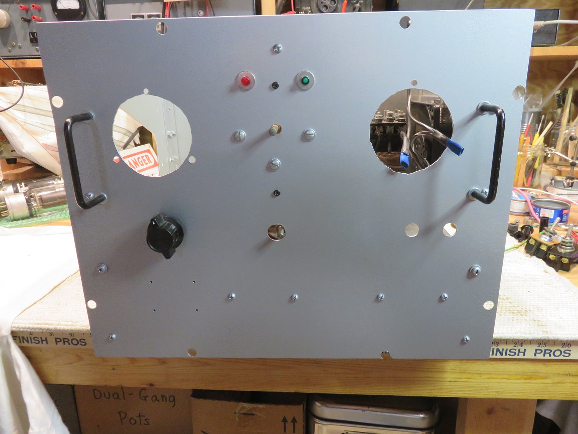
A new front panel was cut using the old panel as a template and various brackets were cut and/or bent as required.
The power supply primary AC circuit is protected by a 15 amp fuse and a 20 amp varistor reduces the filament transformer turn-on surge.
The HV is switched separately from the filament supply and cannot be energized unless the filaments are on. The HV transformer primary windings are served by another 20 amp varistor. Filament and HV LED indicator lights are included.
The filaments are powered by a 10-0-10 volt, 10 amp transformer I found at a ham fest. It’s old but seems OK. See the HV power supply schematic for details; a description is below:
The Plate current meter is inserted in the Filament Transformer’s center tap which is connected to ground through an 0.05 ohm 25 watt wire-wound resistor. This resistor serves as a very low ohm shunt for the plate current meter and reduces the filament voltage slightly (see below).
Power=I squared * R, so (10amp*10amp*.05ohm) = 5 watts through a 25 watt resistor, which seems safe. The meter is also protected with diodes and bypassed by a capacitor. See the meter diagram.
The filament transformer was originally designed for a 110 volt primary and we now have a 120 volt line voltage which is a 9% increase. This will cause the secondary voltage to be 10.9 volts, rather than the desired 10.0 volts.
The meter shunt resistor mentioned above will decrease the filament voltage by 0.5 volts, so now the filament voltage will be 10.4 volts; still a bit high. It might prove necessary to insert a second 0.05 ohm resistor in the filament center tap, or increase the meter shunt resistor from 0.05 to 0.1 ohms. We’ll adjust the filament voltage by observing and measuring with a known accurate meter, and adding resistance as needed to keep it at a conservative level.
The slight resistance of the filament primary varistor will also have a very small effect on the secondary voltage; thus we will have to fiddle with this to bring the voltage to the desired level.
The RF deck uses a Barker and Williamson FC-30 RF filter and bypass caps following the filament transformer, to keep RF from leaking back into the filament transformer. The FC-30 is overkill (FC-15 is sufficient) but that is what I had.
The FC-30 has two independent bifilar windings, so that each winding can serve one tube’s filament. Here, we have put the two sets of windings in series, doubling the inductance of the filter to allow it to work on 1.8mc (otherwise it is rated only to 3.5mc).
The HV power supply uses two repurposed 1200 watt microwave oven transformers (MOT) for the plate supply. The MOT 3 volt filament windings and the current-limiting shunts were removed. Using a single MOT “barefoot,” with no primary winding surge protection, can sometimes cause a house circuit breaker to pop as sometimes startup occurs during a certain part of the AC phase, causing an excessive amperage draw.
These xfmrs cost nothing and, when their primaries are put in series, the two primaries in series provide enough AC resistance to not pop circuit breakers, by slowing the instantaneous AC start-up current.
The HV switch-on AC current surge will also be buffered by use of a varistor in the primary winding’s AC lead.
20 amp filament and HV switches are used, with green and red 120 VAC LED indicators.
The two MOT secondaries are wired in series with the grounded ends lifted and not grounded. With the primary windings in series, each secondary outputs about ~1,000 volts rather than the usual ~2,000. This should reduce any strain on the secondary insulation.
Wiring the secondaries this way provides a 1000-1000 volt secondary (no center tap used) so that a full-wave bridge rectifier circuit can be used. This provides better voltage regulation than a voltage doubler circuit.
The HV wire from the transformer secondaries to the rectifier circuit is 40KV 20 gauge wire taken from an old tube-type TV. This, in turn, is threaded through neoprene tubing for double insulation.
The MOT secondaries feed a bridge rectifier of four 2A, 20KV diodes having a large surge current rating. These cost $8, delivered. The immediate (before the filter caps) DC output is protected by a 750 ma microwave oven fuse followed by a 50 ohm, 10 watt “glitch” resistor.
This fuse is enclosed in a protective container. If it ever blows, we don’t want shards of glass sprayed all over the amplifier’s cabinet. Never use a 120 VAC fuse for this purpose!
The “glitch” resistor’s purpose is to absorb some of the current flow should a brief overload occur. A dead short will blow the fuse but an instantaneous minor one might not as the resistor will absorb some of the surge.
With a capacitive filter, power supply voltage is expected to be about 2,000v x 1.4 = 2800 volts, slightly above the tube manufacturer’s 2500 volt specification. We will see how it actually turns out and I’m sure there will be some voltage sag under load.
The ground return of the bridge rectifier goes directly to chassis ground. Should the HV be too high, a high-wattage resistor could be installed here to bring the voltage down.
I’ve seen the 813 tube operated at over 3,000 volts, but this seems excessive to me and I prefer to stay in the 2,500 – 2,600 volt range.
The HV capacitive-input filter system consists of seven sections of 300 mfd/450 volt electrolytics in series, for a 3150 volt total capability. Each of these caps are actually two 150 mfd units in parallel. 300 divided by 7 yields 43 mfd total filtering capacitance which should be OK. Many older designs used only 20 mfd.
Each cap will be stressed to 88% of its rated voltage which is a little higher than I like but should be OK. Normally, I don’t like to exceed 75% but these are a good grade of cap.
Each section is shunted by a 20K 15W resistor (140K ohms of shunt/bleeder total). This results in a total of 43 mfd of filter capacity and 20 ma of bleeder current through the equalizers. The voltage drop across each resistor is about 400 volts at 20ma, or 8 watts of heat.
In addition, a string of 5, 100K ceramic wire-wound resistors goes directly from B+ to ground. These act as a very slow safety bleed in case one of the equalizer resistors opens up – when the amp is turned off with a failed equalizer resistor, the voltage decay will be extremely slow, indicating the resistor problem.
The 43 mfd of filter capacity, the 1200 watt rating of each of the transformers, the full-wave bridge rectifier circuit and the 20 ma of bleeder current should combine to provide a decent AC ripple on the B+ line.

Plate voltage is measured by connecting the metering circuit to the last stage of the electrolytic filter system. This presents about 400 volts to the metering circuit rather than using a string of megohm resistors to tap into the HV line.
The picture shows the rectifiers mounted across a home-made printed circuit board. The filter caps and equalizer resistors are across the bottom. The circuit board’s traces were made using a Dremel tool; crude but effective.
A word about safety: Good design requires some method of ensuring that it is not possible to open the amplifier and stick your fingers into it while the B+ is on. 2800 volts is lethal!
There is no lid to this amplifier and it requires unscrewing eight front-panel screws to open the amplifier and slide it out of the cabinet. The B+ should have bled down to zero in the time it takes to remove the screws.
We have to assume that the operator will unplug the amp before trying to remove it from its cabinet…
Output Network: I was originally going to use a variable coil and a turns counter for the pi output network. Due to space limitations the design was changed to a fixed, tapped B&W coil of excellent quality and a top-grade band switch; all from the junque box.
The Tune Capacitor is 200pf and the Load Capacitor is a three section one of 1800 total pf with quality receiver spacing. These caps might need auxilliary padding caps to reach 160M should I decide to go there.
I have two RF chokes for the HV line…the tall cylindrical one came out of a junked Henry 2K amateur amplifier and I will use that one. The second, pi-wound one in the photo, from the aforementioned 10KW AM transmitter, could also be used. I might also follow the RF choke with a second one and a second bypass capacitor, designed for UHF, in the “cold” side of the B+ line.
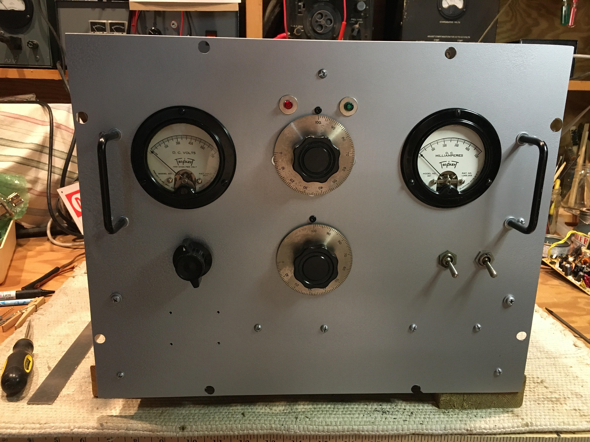
Meters are old round Triplett types; one for HV and another for Plate Current. Both meters are protected with diodes and bypassed with .01 caps and have copper shields in hopes of keeping too much RF from escaping through the meters.
A band-specific tuned input network is not used since a single 813 presents about 200 ohms and two in parallel present roughly 100 ohms to the driver. Most driver xmtrs, especially tube ones, will tolerate that, working into about a 2:1 SWR.
Progress photos and other data will be added to this page…and when the project is complete, tested and in service, the proposed schematics will be replaced with “as-built” schematics.