DX-60B Restoration
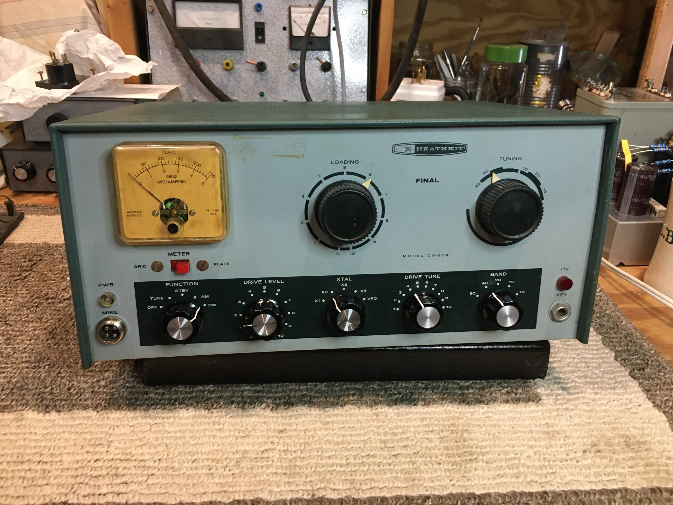
I purchased a used DX-60B of unknown provenance, which had been stored for some years. The upper works of the chassis were in good condition with no significant corrosion on the steel chassis. The panel is excellent.
Apparently it was used for CB operation as the only crystal in it was an HC-17 for a 27.120 MHz CB frequency. I have three FT-243’s for the 40 meter CW band so will begin with those and find a way to adapt a BC-221 to replace crystals, for all-band operation, build a VFO or perhaps purchase an old one.
The person who built it did an excellent job – almost picture book wiring; probably better than I would have done!
Restoration:
1) Checking and reseating the tubes revealed that the 12AX7 first audio stage was totally dead – the filament was burned out, which is unusual. It was replaced with one having excellent emission and the other tubes were OK.
2) All electrolytic capacitors were faulty and growing chemical whiskers, so they were replaced with modern units. The four 40uf/450V caps in the B+ supply were replaced with 100uf/450V units, as were the two in the bias supply. The 20uf in the audio circuit was replaced with two 10uf in parallel.
3) The other capacitors were not checked as disc ceramic types are usually OK and the few plastic tubular types appeared to be in good condition. Later testing revealed no problems with these.
4) All B+ and Bias rectifier diodes were replaced with modern units, as one had failed.
5) The 10 ohm “glitch” resistor in the bias supply had exploded; this was hard to see as it was hidden underneath another resistor. This was replaced with a 12 ohm wire-wound junkbox resistor of higher wattage. It is suspected that the failure of the bias supply electrolytic capacitor caused this, or that when the 12AX7 filament opened, it might have shorted a tube element. Just speculation.
6) The function switch would not turn but was otherwise in good condition. Spraying its detent section with contact cleaner and some light lubrication oil fixed this. It’s still stiff but works OK.
7) The old 2-conductor power cord was somewhat stiff. It would probably have been OK to use but it was replaced with a 3-conductor cord and a PC-style plug-in socket. The socket is mounted where the old can electrolytic was. The steel chassis is too difficult to drill and file; or I would have installed the socket in the normal fashion in the chassis’ back apron. This is not a museum-quality unit so putting the socket where I did is not a problem. The original 120VAC circuit breaker was intact and remains in use.
8) After the repairs were made the unit was connected to a dummy load, brought up on a variac and tuned up in accordance with the instructions in the manual. It achieved a full 150 MA CW input which is about 90 watts input.
9) No microphone was included with the set and the DX-60B requires a high impedance one. I had a 55 year-old Yaesu YD-846 mike which required a four-conductor plug socket (the xmtr uses a single conductor coaxial socket) so I removed the original socket and replaced it with the new, 4-conductor one. This also makes provision for a future conversion to a PTT scheme. I got no output on AM so I don’t yet know if the microphone is the problem or if there is some difficulty in the modulation circuit. That will be determined later, when I have a known-good microphone.
10) The MA meter works well but its plastic cover is a bit yellowed from exposure to light. Not having an exact replacement, or being able to clean off the yellowed plastic, it remains in place.
11) The bottom row of knobs was replaced by more modern-looking ones since some original ones were cracked.
This unit will pair nicely with my Drake 2A receiver; making a good “nostalgia” station. I need to create a device to allow switching my Keyer from the DX-60B to a Yaesu without having to plug and unplug the Keyer.
To use the DX-60B with the Drake 2A a T/R switch will be required. A MOSFET-based T/R switch will likely be built and used, or an old electro-mechanical relay that I have might do. The fast-acting MOSFET device is preferred so that break-in CW can be used. Another project…sigh.