6AG7-6AG7-6L6 Project Page
[otw_shortcode_button href=”https://www.w4npn.net/” size=”large” icon_position=”left” shape=”round” color_class=”otw-blue”]Return to W4NPN’s Homepage[/otw_shortcode_button]
Update, 12/11/2018: This project began as an amplifier to increase the output of my BC-221 heterodyne frequency meter by feeding that into a 6AG7 first stage, followed by a 6AG7 buffer and ending in a 6L6 final amplifier. But it morphed into a standard crystal-controlled three tube transmitter. I finished this little xmtr and the 6L6 produced 16-18 watts output with 340v on the plate. It’s a nice little transmitter and will be a good companion to a 6SN7-6SN7-6V6 regenerative receiver that I plan to build into a very nice Bud Box containing a professionally built heterodyne frequency meter that must be 60+ years old but which is in excellent condition. I have two BC-221 and one LM-8 frequency meters so don’t need a third one.
—————————————————————————
The original 6AG7-6AG7-6L6 Project info is below:
I haven’t built a transmitter since 1972, when I built a 4-1000A KW linear amplifier while on Midway Island. I used that with an early model FT-101 for 32 years until the linear’s power transformer shorted and then I gave it away. Later, I disposed of the ancient FT-101 (it still worked) and purchased a smaller FT-840.
I have been slowly transitioning to home-built gear and have always wanted to build a little 6AG7 – 6L6 transmitter. I know that a thousand or more have been built…it’s just a nostalgia thing and I had all the parts in my large junk box. I have a restored BC-221 Heterodyne Frequency Meter on the operating bench and I thought I should be able to use it as the VFO.
This has been done by many and there are several web articles about it. I have them if you want copies. The output of a BC-221 is extremely low; and insufficient to replace a crystal in the 6AG7 stage so it needs to be increased. The 1947 Vol 11 “West Coast Handbook” contains a schematic for doing this and it can be seen here. It uses an extra 6AG7 to boost the output of the BC-221, which is then fed into a conventional 6AG7 – 6L6 circuit. Another version of this circuit, published by ARRL, used 6AC7’s but these have a gm of only 4300, compared to the 6AG7’s 9,000.
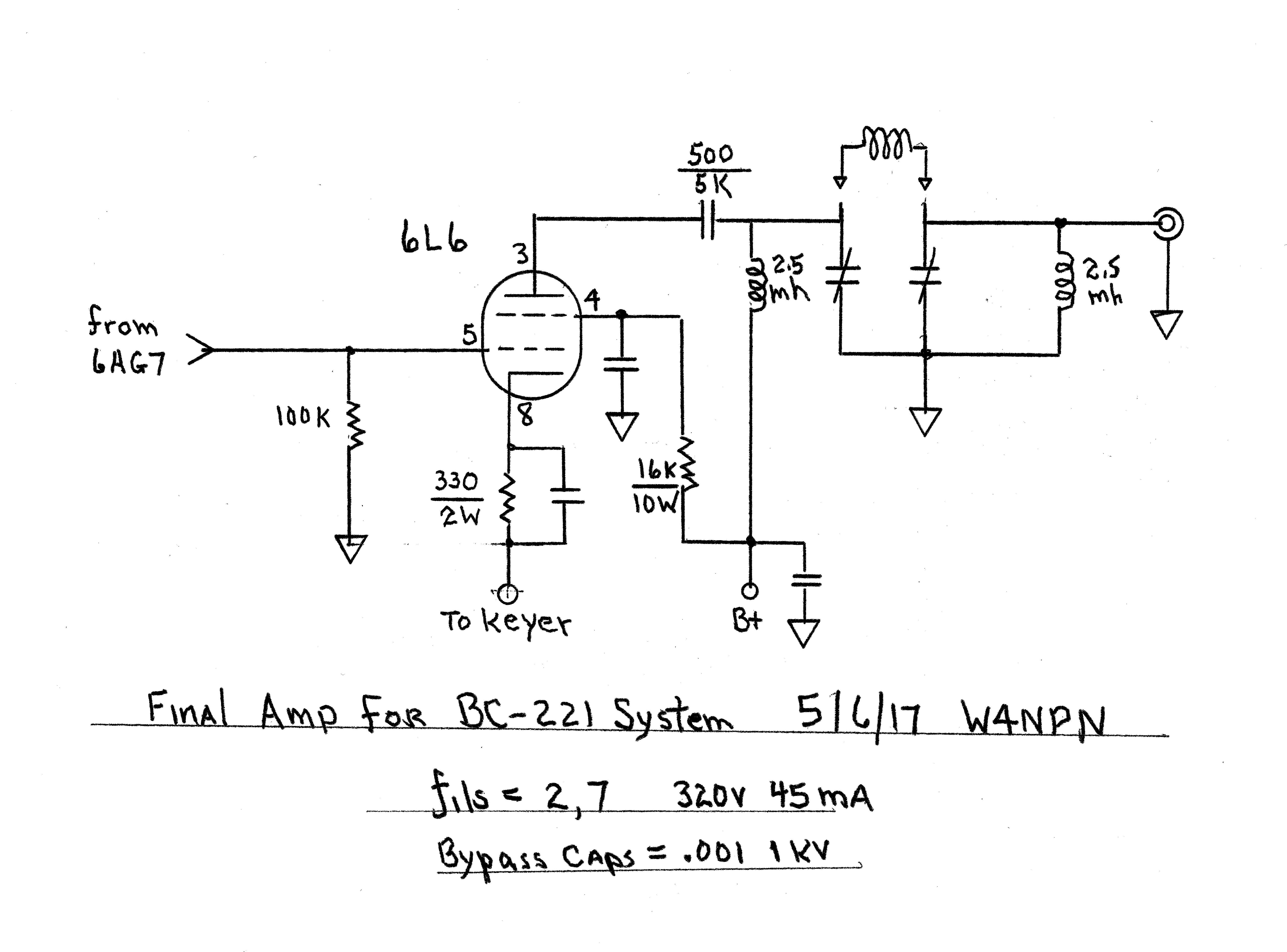
My version is similar to the 1947 version. I changed the P.A. output from a link to a pi network circuit using a variable inductor/turns counter (from an old military unit) and have made some minor component changes. The whole thing is a junkbox special from parts that have fallen into my junkbox over the years. Also, the 1947 circuit runs the 6AG7’s at a regulated 150 volts on the plates and 300 volts on the 6L6 plate. I am running 340 volts on the 6L6 plate and 250 volts on the 6AG7’s. This might be changed later after I take the transmitter off my utility power supply and connect it to a permanent one on the operating bench.
It is not obvious to me why the 6AG7’s need a regulated voltage if the power supply is “stiff.” My transmitted signal keys cleanly when the 6L6 cathode is keyed because the BC-221 has its own voltage regulation scheme for the oscillator/buffer and there are now two 6AG7 buffer/amplifier stages between the BC-221 and the 6L6.
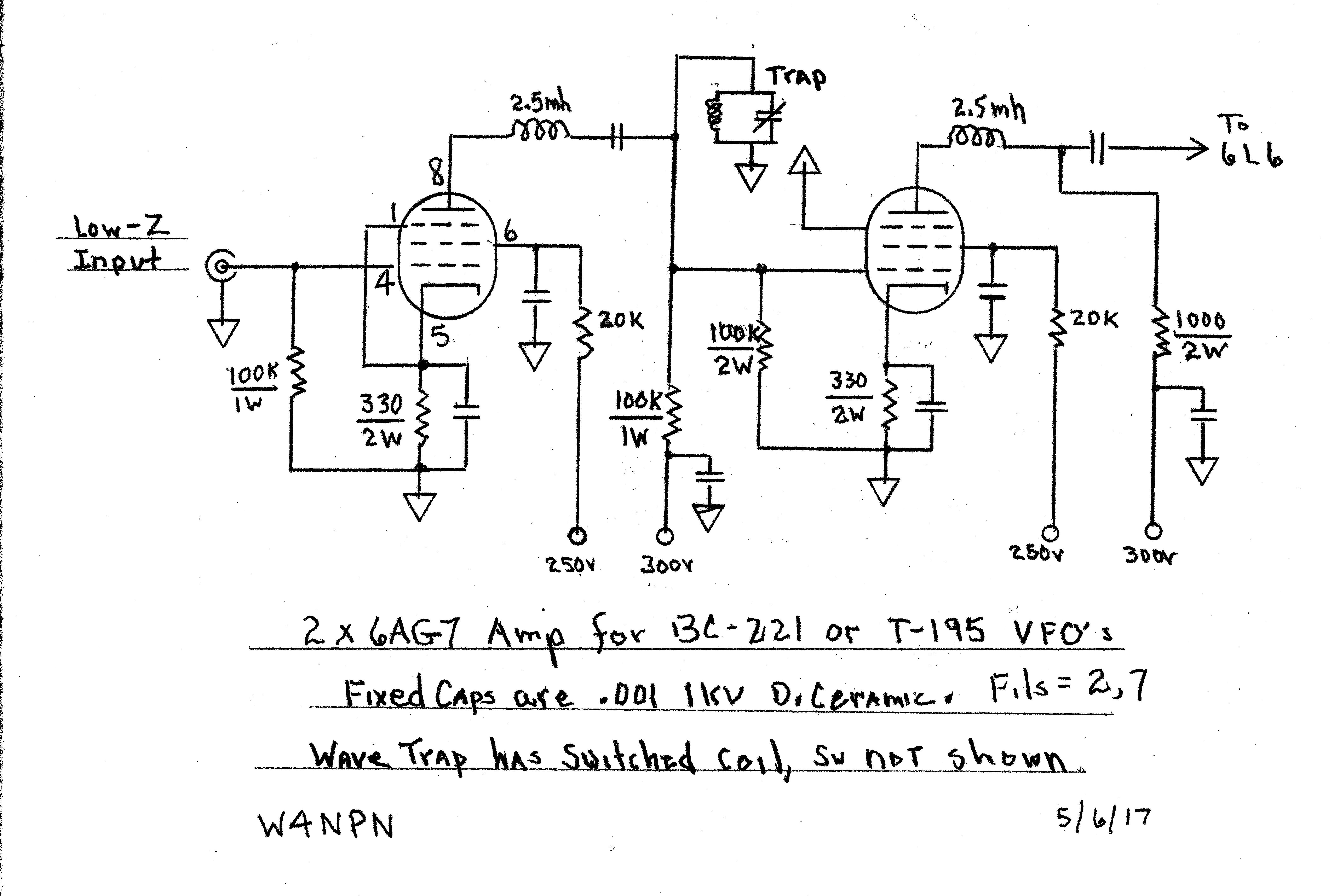
I also added a “wavetrap” (parallel coil & cap to ground) from the plate of the first 6AG7, in order to remove unwanted signals that the harmonic-rich BC-221 produces. When I’m on 3520 kc, I don’t want to also be transmitting on 7040, 14,080 and 10,560 kc, for instance. For ham use, the BC-221 will produce a strong signal in the 80 meter band which can be multiplied up to the other bands. Click here to see the current schematic for the first two 6AG7’s, and the following 6L6 stage schematic is here.
So far, I’ve wired the little transmitter and it works, with about 15 watts input with 340 volts on the 6L6 plate. I need to finish some work, adding capacitance to the loading capacitor. I’ve also decided that I need a dedicated meter to read the Cathode current – reading the utility power supply’s MA meter is hard as it includes the current consumed by the 6AG7 screens and plates as well as the 6L6 screen. I’ll take care of that later. Fully loaded it indicates about 30 ma for the two 6AG7’s plus 45 ma for the 6L6 plate+screen.
There is one problem I just realized: The wave trap I installed has three switchable coils, tuned by a variable capacitor – one coil for 80 meters, one for 40-30 and one for 20 meters. When the BC-221 is on 3520 kc, a strong harmonic appears on 10,560 kc and the wavetrap does not kill this harmonic. The harmonics on 7040 and 14080 are 30 or more db down from the 80 meter signal as measured by my Yaesu 840’s S-meter. I’m not sure how to kill the 10560 kc harmonic but I’ll figure that out before putting the unit into service. When I tune to 7040 or 14080, the 10560 kc strong harmonic does not change.
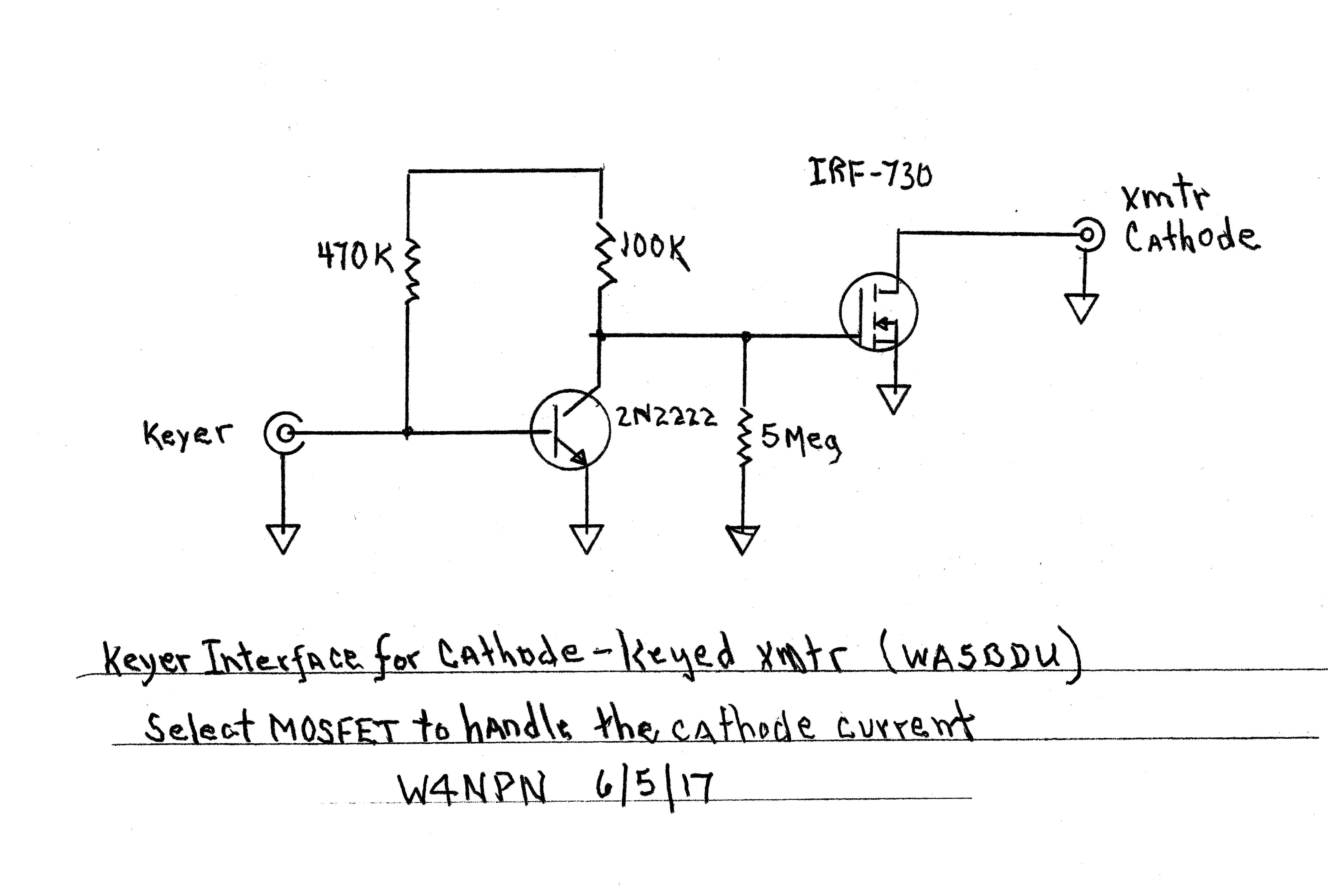
I’m no good with a J-38 key any more and use a keyer. The solid-state keyer cannot be plugged into the cathode of the 6L6 due to the 50 volts appearing there. So I will build an interface that uses an IRF-730 driven by a 2n2222, to key the cathode. Any n-channel mosfet that can handle the current can be used. The schematic for this can be found here.
I will probably build the keyer interface into a small box and might include a switchable (in/out) meter to measure cathode current. The schematics are also included below on this page. Note that the 2.5mh RF choke is shown in the wrong place – it should be in the B+ feed, above the voltage dropping resistors.
.
.